Page Summary
-
The Augmented Faces API in AR Foundation allows you to render assets on human faces in your app.
-
Faces are detected and managed by the ARFaceManager, which creates ARFace objects to track them and provides updates through the facesChanged event.
-
Detected faces can be accessed through the ARFace component, providing data like vertices, indices, vertex normals, and texture coordinates.
-
The API provides a center pose, three region poses (left forehead, right forehead, and nose tip), and a 468-point 3D face mesh for each detected face.
-
The 3D face mesh vertices and normals can be accessed, and tools like Blender can be used to visualize the index numbers of individual vertices.
Learn how to use Augmented Faces to render assets on top of human faces in your own app.
Prerequisites
Make sure that you understand fundamental AR concepts and how to configure an ARCore session before proceeding.
Detect faces
Faces are represented by ARFace objects that are created, updated, and removed by the ARFaceManager. Once per frame, the ARFaceManager invokes a facesChanged event that contains three lists: faces that have been added, faces that have been updated, and faces that have been removed since the last frame. When the ARFaceManager detects a face in the scene, it will instantiate a Prefab with an ARFace component attached to track the face. The Prefab can be left null.
To set up the ARFaceManager, create a new game object and add the ARFaceManager to it.
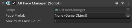
Face Prefab is the Prefab instantiated at the face’s center pose. Maximum Face Count represents the maximum amount of faces that can be tracked.
Access detected faces
Access detected faces through the ARFace component, which is attached to the Face Prefab. ARFace provides vertices, indices, vertex normals, and texture coordinates.
Parts of a detected face
The Augmented Faces API provides a center pose, three region poses, and a 3D face mesh.
Center pose
The center pose, which marks the center of a user’s head, is the origin point of the Prefab instantiated by the ARFaceManager. It is located inside the skull, behind the nose.
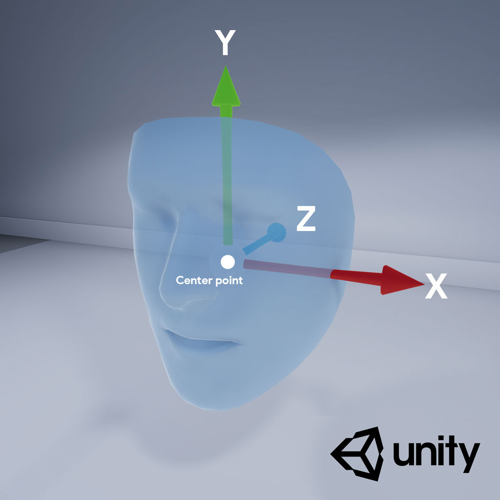
The axes of the center pose are as follows:
- The positive X-axis (X+) points toward the left ear
- The positive Y-axis (Y+) points upwards out of the face
- The positive Z-axis (Z+) points into the center of the head
Region poses
Located on the left forehead, right forehead, and tip of the nose, region poses mark important parts of a user’s face. The region poses follow the same axis orientation as the center pose.
To use the region poses, downcast the ARFaceManager’s subsystem to ARCoreFaceSubsystem and use subsystem.GetRegionPoses() to obtain pose information for each region. For an example of how to do this, see Unity’s usage sample on GitHub.
3D face mesh
The face mesh consists of 468 points that make up a human face. It is also defined relative to the center pose.
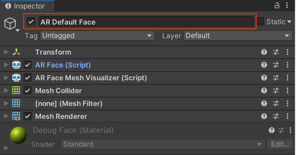
To visualize the face mesh, attach an ARFaceMeshVisualizer to the Face Prefab. The ARFaceMeshVisualizer will generate a Mesh that corresponds to the detected face, setting it as the mesh in the attached MeshFilters and MeshColliders. Use a MeshRenderer to set the Material used to render the face.
The AR Default Face Prefab renders a default material on detected face meshes.

Follow these steps to start using the AR Default Face:
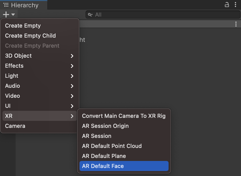
- Set up an
ARFaceManager. In the Hierarchy tab, use + > XR > AR Default Face to create a new face object. This object is temporary and can be deleted once you create the Face Prefab.
Access the AR Default Face in the Inspector.
Drag the newly created AR Default Face from the Hierarchy tab into the Project Assets window to create a Prefab.
Set the newly created Prefab as the Face Prefab in the
ARFaceManager’s Face Prefab field.In the Hierarchy tab, delete the face object, as it's no longer needed.
Access individual vertices of the face mesh
Use face.vertices to access the positions of the face mesh’s vertices. Use face.normals to access the corresponding vertex normals.
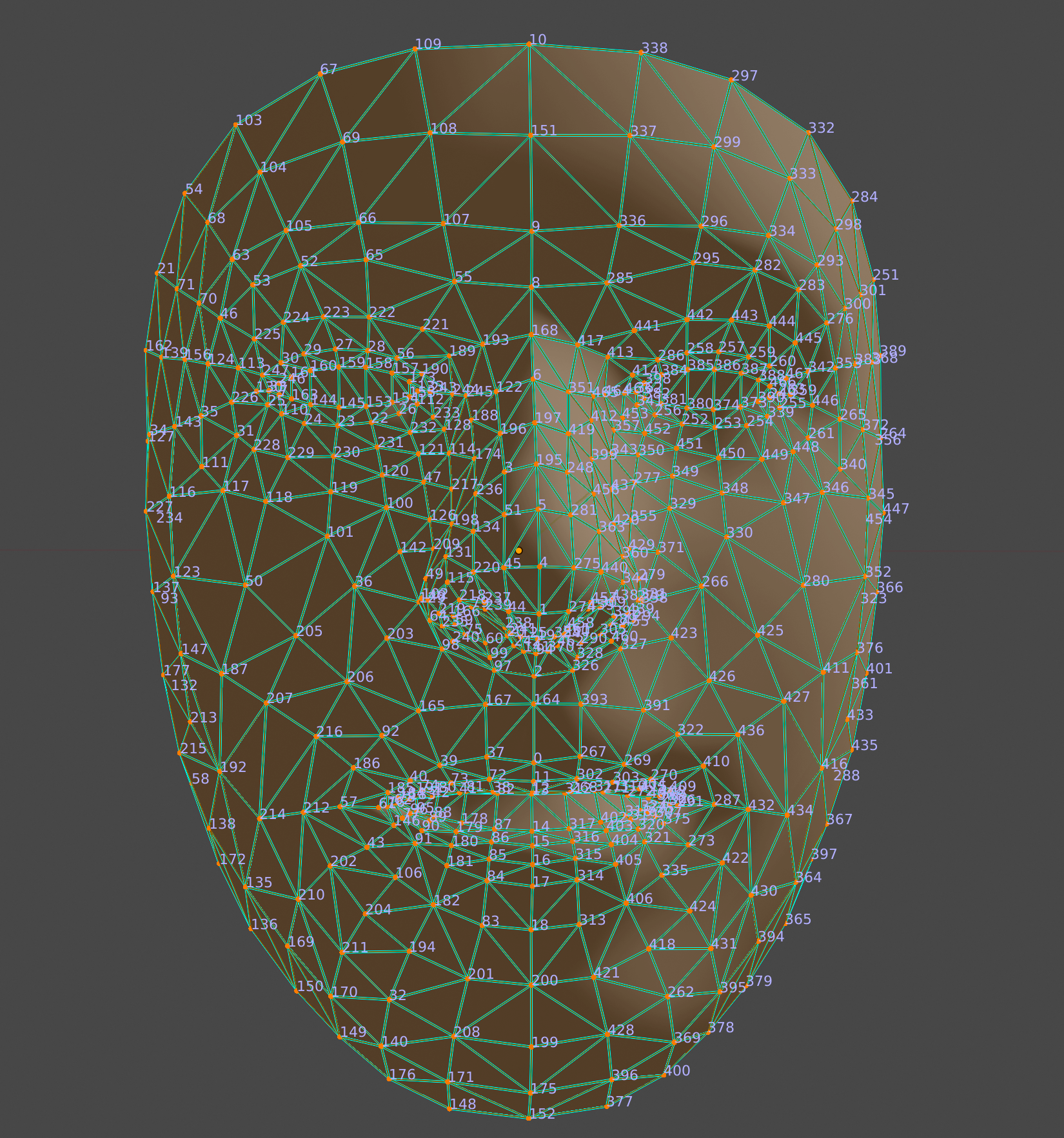
Visualize individual vertices of the face mesh
You can use Blender to easily view the index numbers that correspond to a face mesh’s vertices:
- Open Blender and import
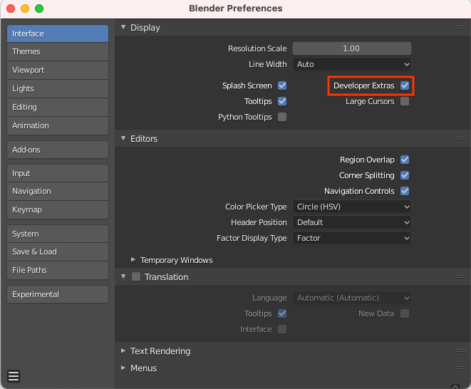
canonical_face_mesh.fbxfrom GitHub. - Navigate to Edit > Preferences > Interface.
Under the Display menu, select Developer Extras.
Select the face by clicking it in the 3D viewport, and press Tab to enter Edit Mode.
Open the drop-down menu next to the Overlays viewport and select Indices.
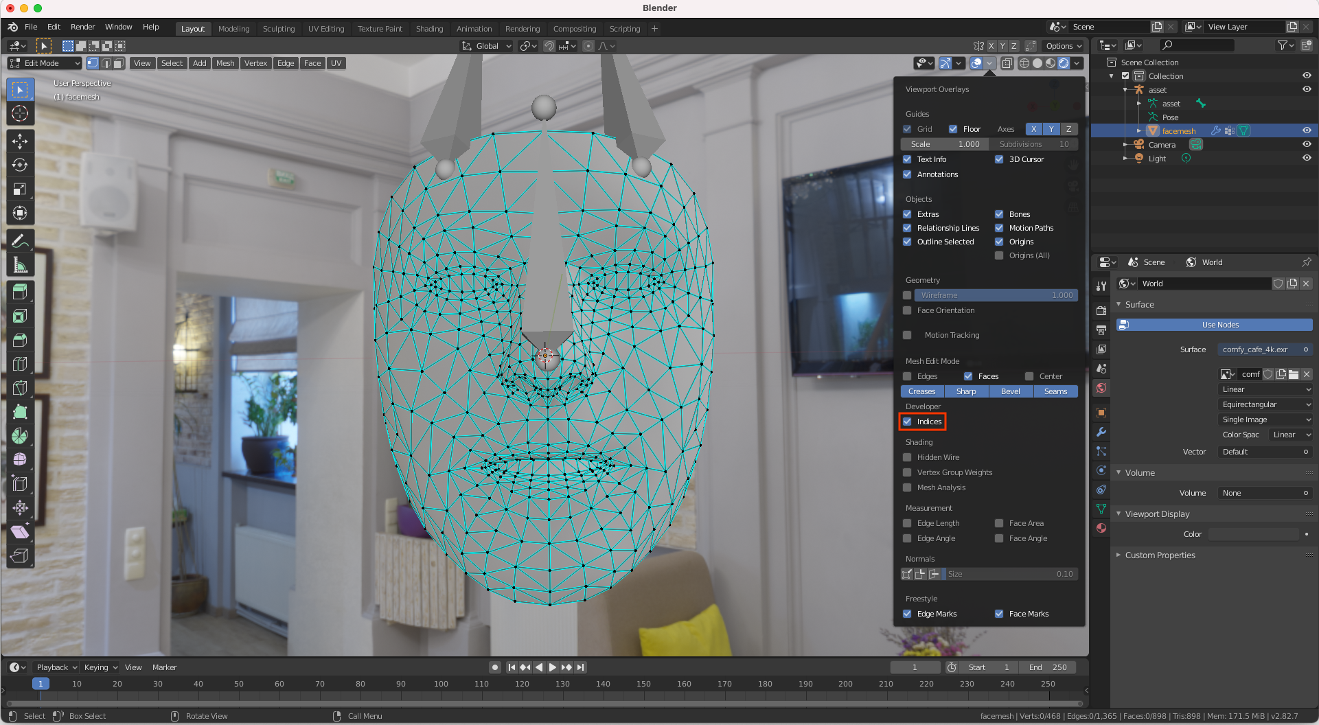
Highlight the vertex whose index number you would like to determine. To highlight all vertices, use Select > All.