Page Summary
-
Sceneform materials utilize
.sfmor custom.matfiles to define the visual appearance of surfaces, controlling aspects like lighting, color, and texture. -
Material definitions have a structured format with
material, optionalvertex, andfragmentblocks, allowing for customization through shader code. -
Sceneform provides three main material models: Lit (physically-based), Cloth (fabric-specific), and Unlit (for pre-lit elements or debugging).
-
The Lit model offers extensive properties for realistic rendering, including base color, metallic, roughness, reflectance, and clear coat settings.
-
Filament expects colors in linear space with pre-multiplied alpha, ensuring accurate visual representation.
Sceneform provides default material definitions (.sfm) to make it easy for
developers to get great looking results. Developers who want to deeply customize
the way their assets look can create their own material definitions (*.mat
files) and apply them to their assets by specifying the source
attribute in the asset definition.
Core concepts
- Material
- A material defines the visual appearance of a surface. To completely
describe and render a surface, a material provides the following
information:
- Material model
- Set of use-controllable named parameters
- Raster state (blending mode, backface culling, etc.)
- Vertex shader code
- Fragment shader code
- Material model
- Also called shading model or lighting model, the material model defines the intrinsic properties of a surface. These properties have a direct influence on the way lighting is computed and therefore on the appearance of a surface.
- Material definition
- A text file that describes all the information required by a material. This
page describes the structure and format of (
*.mat) material definition files.
Material definitions
A material definition is a text file that describes all the information required by a material:
- Name
- User parameters
- Material model
- Required attributes
- Interpolants (called variables)
- Raster state (blending mode, etc.)
- Shader code (fragment shader, optionally vertex shader)
Format
The material definition format is a format loosely based on JSON that we call JSONish. At the top level a material definition is composed of 3 different blocks that use the JSON object notation:
material {
    // material properties
}

vertex {
    // vertex shader, optional
}

fragment {
    // fragment shader
}
A minimum viable material definition must contain a material block and a
fragment block. The vertex block is optional.
Differences with JSON
In JSON, an object is made of key/value pairs. A JSON pair has the following syntax:
"key" : value
Where value can be a string, number, object, array or a literal (true, false
or null). While this syntax is perfectly valid in a material definition, a
variant without quotes around strings is also accepted in JSONish:
key : value
Quotes remain mandatory when the string contains spaces.
The vertex and fragment blocks contain unescaped, unquoted GLSL code, which
is not valid in JSON.
Single-line C++ style comments are allowed.
The key of a pair is case-sensitive.
The value of a pair is not case-sensitive.
Example
The following code listing shows an example of a valid material definition. This
definition uses the lit material model, uses the default opaque
blending mode, requires that a set of UV coordinates be presented in the
rendered mesh and defines 3 user parameters. The following sections of this
document describe the material and fragment blocks in detail.
material {
    name : "Textured material",
    parameters : [
        {
           type : sampler2d,
           name : texture
        },
        {
           type : float,
           name : metallic
        },
        {
            type : float,
            name : roughness
        }
    ],
    requires : [
        uv0
    ],
    shadingModel : lit,
    blending : opaque
}

fragment {
    void material(inout MaterialInputs material) {
        prepareMaterial(material);
        material.baseColor = texture(materialParams_texture, getUV0());
        material.metallic = materialParams.metallic;
        material.roughness = materialParams.roughness;
    }
}
Material block
The material block is mandatory block that contains a list of property pairs to describe all non-shader data.
name
- Type
string- Value
- Any string. Double quotes are required if the name contains spaces.
- Description
- Sets the name of the material. The name is retained at runtime for debugging purpose.
material {
    name : stone
}

material {
    name : "Wet pavement"
}
shadingModel
- Type
string- Value
- Any of
lit,cloth,unlit. Defaults tolit. - Description
- Selects the material model as described in the Material models section.
material {
    shadingModel : unlit
}
parameters
- Type
- array of parameter objects
- Value
Each entry is an object with the properties
nameandtype, both ofstringtype. The name must be a valid GLSL identifier. The type must be one of the types described in the table below.Type Description bool Single boolean bool2 Vector of 2 booleans bool3 Vector of 3 booleans bool4 Vector of 4 booleans float Single float float2 Vector of 2 floats float3 Vector of 3 floats float4 Vector of 4 floats int Single integer int2 Vector of 2 integers int3 Vector of 3 integers int4 Vector of 4 integers sampler2d 2D texture samplerExternal External texture. For more information, see ExternalTexture and setExternalTexture() - Samplers
Sampler types can also specify a
format(defaults tofloat) and aprecision(defaults todefault). The format can be one ofint,float. The precision can be one ofdefault(best precision for the platform, typicallyhighon desktop,mediumon mobile),low,medium,high.- Description
Lists the parameters required by your material. These parameters can be set at runtime using Sceneform's material API. Accessing parameters from the shaders varies depending on the type of parameter:
- Samplers types: use the parameter name prefixed with
materialParams_. For instance,materialParams_myTexture. - Other types: use the parameter name as the field of a structure
called
materialParams. For instance,materialParams.myColor.
- Samplers types: use the parameter name prefixed with
material {
    parameters : [
        {
           type : float4,
           name : albedo
        },
        {
           type      : sampler2d,
           format    : float,
           precision : high,
           name      : roughness
        },
        {
            type : float2,
            name : metallicReflectance
        }
    ],
    requires : [
        uv0
    ],
    shadingModel : lit,
}

fragment {
    void material(inout MaterialInputs material) {
        prepareMaterial(material);
        material.baseColor = materialParams.albedo;
        material.roughness = texture(materialParams_roughness, getUV0());
        material.metallic = materialParams.metallicReflectance.x;
        material.reflectance = materialParams.metallicReflectance.y;
    }
}
requires
- Type
- array of
string - Value
- Each entry must be any of
uv0,uv1,color,tangents. - Description
- Lists the vertex attributes required by the material. The
positionattribute is automatically included and does not need to be specified. Thetangentsattribute is automatically required when selecting any shading model that is notunlit. See the shader sections of this document for more information on how to access these attributes from the shaders.
material {
    parameters : [
        {
           type : sampler2d,
           name : texture
        },
    ],
    requires : [
        uv0
    ],
    shadingModel : lit,
}

fragment {
    void material(inout MaterialInputs material) {
        prepareMaterial(material);
        material.baseColor = texture(materialParams_texture, getUV0());
    }
}
variables
- Type
- array of
string - Value
- Up to 4 strings, each must be a valid GLSL identifier.
- Description
- Defines custom interpolants (or variables) that are output by the material's
vertex shader. Each entry of the array defines the name of an interpolant.
The full name in the fragment shader is the name of the interpolant with the
variable_prefix. For instance, if you declare a variable calledeyeDirectionyou can access it in the fragment shader usingvariable_eyeDirection. In the vertex shader, the interpolant name is simply a member of theMaterialVertexInputsstructure (material.eyeDirectionin your example). Each interpolant is of typefloat4(vec4) in the shaders.
material {
    name : Skybox,
    parameters : [
        {
           type : sampler2d,
           name : skybox
        }
    ],
    variables : [
         eyeDirection
    ],
    vertexDomain : device,
    depthWrite : false,
    shadingModel : unlit
}

fragment {
    void material(inout MaterialInputs material) {
        prepareMaterial(material);
        float theta = acos(variable_eyeDirection.y);
        float phi = atan(variable_eyeDirection.z / variable_eyeDirection.x) +
            (variable_eyeDirection.x > 0.0 ? 0.0 : PI);
        material.baseColor = texture(materialParams_skybox,
            vec2((phi + PI / 2.0) / (2.0 * PI), theta / PI));
    }
}

vertex {
    void materialVertex(inout MaterialVertexInputs material) {
        float3 p = getPosition().xyz;
        float3 u = mulMat4x4Float3(getViewFromClipMatrix(), p).xyz;
        material.eyeDirection.xyz = mulMat3x3Float3(getWorldFromViewMatrix(), u);
    }
}
blending
- Type
string- Value
- Any of
opaque,transparent,fade,add,masked. Defaults toopaque. - Description
Defines how/if the rendered object is blended with the content of the render target. The possible blending modes are:
- Opaque: blending is disabled, the alpha channel of the material's output is ignored.
- Transparent: blending is enabled. The material's output is alpha composited with the render target, using Porter-Duff's source over rule. This blending mode assumes pre-multiplied alpha.
- Fade: acts as
transparentbut transparency is also applied to specular lighting. Intransparentmode, the material's alpha values only applies to diffuse lighting. This blending mode is useful to fade lit objects in and out. - Add: blending is enabled. The material's output is added to the content of the render target.
- Masked: blending is disabled. This blending mode enables alpha masking. The alpha channel of the material's output defines whether a fragment is discarded or not. See the maskThreshold section for more information.
material {
    blending : transparent
}
vertexDomain
- Type
string- Value
- Any of
object,world,view,device. Defaults toobject. - Description
Defines the domain (or coordinate space) of the rendered mesh. The domain influences how the vertices are transformed in the vertex shader. The possible domains are:
- Object: the vertices are defined in the object (or model) coordinate space. The vertices are transformed using the rendered object's transform matrix
- World: the vertices are defined in world coordinate space. The vertices are not transformed using the rendered object's transform.
- View: the vertices are defined in view (or eye or camera) coordinate space. The vertices are not transformed using the rendered object's transform.
- Device: the vertices are defined in normalized device (or clip) coordinate space. The vertices are not transformed using the rendered object's transform.
material {
    vertexDomain : device
}
interpolation
- Type
string- Value
- Any of
smooth,flat. Defaults tosmooth. - Description
- Defines how interpolants (or variables) are interpolated between vertices.
When this property is set to
smooth, a perspective correct interpolation is performed on each interpolant. When set toflat, no interpolation is performed and all the fragments within a given triangle will be shaded the same.
material {
    interpolation : flat
}
culling
- Type
string- Value
- Any of
none,front,back,frontAndBack. Defaults toback. - Description
- Defines which triangles should be culled: none, front-facing triangles, back-facing triangles or all.
material {
    culling : none
}
colorWrite
- Type
boolean- Value
trueorfalse. Defaults totrue.- Description
- Enables or disables writes to the color buffer.
material {
    colorWrite : false
}
depthWrite
- Type
boolean- Value
trueorfalse. Defaults totrue.- Description
- Enables or disables writes to the depth buffer.
material {
    depthWrite : false
}
depthCulling
- Type
boolean- Value
trueorfalse. Defaults totrue.- Description
- Enables or disables depth testing. When depth testing is disabled, an object rendered with this material will always appear on top of other opaque objects.
material {
    depthCulling : false
}
doubleSided
- Type
boolean- Value
trueorfalse. Defaults tofalse.- Description
- Enables or disables two-sided rendering. When set to
true,cullingis automatically set tonone; if the triangle is back-facing, the triangle's normal is automatically flipped to become front-facing.
material {
    doubleSided : true
}
transparency
- Type
string- Value
- Any of
default,twoPassesOneSideortwoPassesTwoSides. Defaults todefault. - Description
- Controls how transparent objects are rendered. It is only valid when the
blendingmode is notopaque. None of these methods can accurately render concave geometry, but in practice they are often good enough.
The three possible transparency modes are:
default: the transparent object is rendered normally, honoring thecullingmode, etc.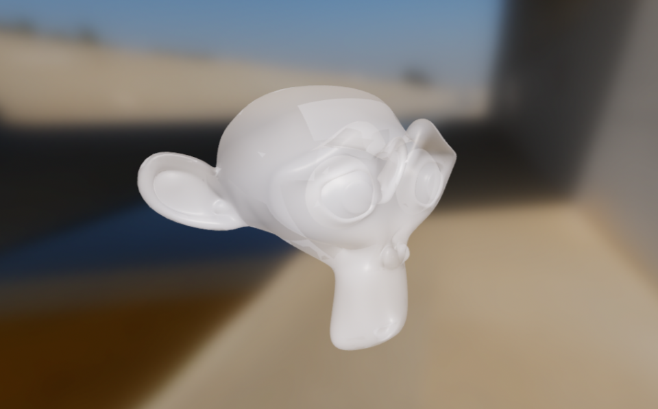
twoPassesOneSide: the transparent object is first rendered in the depth buffer, then again in the color buffer, honoring theculllingmode. This effectively renders only half of the transparent object as shown below.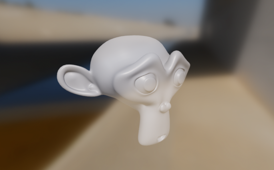
twoPassesTwoSides: the transparent object is rendered twice in the color buffer: first with its back faces, then with its front faces. This mode lets you render both set of faces while reducing or eliminating sorting issues, as shown below.twoPassesTwoSidescan be combined withdoubleSidedfor better effect.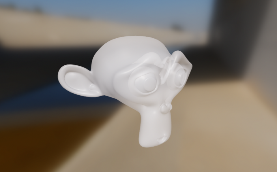
material {
    transparency : twoPassesOneSide
}
maskThreshold
- Type
number- Value
- A value between
0.0and1.0. Defaults to0.4. - Description
- Sets the minimum alpha value a fragment must have to not be discarded when
the
blendingmode is set tomasked. When the blending mode is notmasked, this value is ignored. This value can be used to controlled the appearance of alpha-masked objects.
material {
    blending : masked,
    maskThreshold : 0.5
}
shadowMultiplier
- Type
boolean- Value
trueorfalse. Defaults tofalse.- Description
- Only available in the
unlitshading model. If this property is enabled, the final color computed by the material is multiplied by the shadowing factor (or visibility). This allows to create transparent shadow-receiving objects (for instance an invisible ground plane in AR).
material {
    name : "Invisible shadow plane",
    shadingModel : unlit,
    shadowMultiplier : true,
    blending : transparent
}

fragment {
    void material(inout MaterialInputs material) {
        prepareMaterial(material);
        // baseColor defines the color and opacity of the final shadow
        material.baseColor = vec4(0.0, 0.0, 0.0, 0.7);
    }
}
variantFilter
- Type
- array of
string - Value
- Each entry must be any of
dynamicLighting,directionalLighting,shadowReceiverorskinning. - Description
- Used to specify a list of shader variants that the application guarantees
will never be needed. These shader variants are skipped during the code
generation phase, thus reducing the overall size of the material. Note that
some variants may automatically be filtered out. For instance, all lighting
related variants (
directionalLighting, etc.) are filtered out when compiling anunlitmaterial. Use the variant filter with caution, filtering out a variant required at runtime may lead to crashes.
Description of the variants: - directionalLighting, used when a directional
light is present in the scene - dynamicLighting, used when a non-directional
light (point, spot, etc.) is present in the scene - shadowReceiver, used when
an object can receive shadows - skinning, used when an object is animated
using GPU skinning
material {
    name : "Invisible shadow plane",
    shadingModel : unlit,
    shadowMultiplier : true,
    blending : transparent,
    variantFilter : [ skinning ]
}
Vertex block
The vertex block is optional and can be used to control the vertex shading stage
of the material. The vertex block must contain valid
ESSL 3.0
code (the version of GLSL supported in OpenGL ES 3.0). You are free to create
multiple functions inside the vertex block but you must declare the
materialVertex function:
vertex {
    void materialVertex(inout MaterialVertexInputs material) {
        // vertex shading code
    }
}
This function will be invoked automatically at runtime by the shading system and
gives you the ability to read and modify material properties using the
MaterialVertexInputs structure. This full definition of the structure can be
found in the Material vertex inputs section.
You can use this structure to compute your custom variables/interpolants or to modify the value of the attributes. For instance, the following vertex blocks modifies both the color and the UV coordinates of the vertex over time:
material {
    requires : [uv0, color]
}
vertex {
    void materialVertex(inout MaterialVertexInputs material) {
        material.color *= sin(getTime());
        material.uv0 *= sin(frameUniforms.time);
    }
}
In addition to the MaterialVertexInputs structure, your vertex shading code
can use all the public APIs listed in the
Shader public APIs section.
Material vertex inputs
struct MaterialVertexInputs {
    float4 color;         // if the color attribute is required
    float2 uv0;           // if the uv0 attribute is required
    float2 uv1;           // if the uv1 attribute is required
    float3 worldNormal;   // only if the shading model is not unlit
    float4 worldPosition; // always available
    // variable* names are replaced with actual names
    float4 variable0;     // if 1 or more variables is defined
    float4 variable1;     // if 2 or more variables is defined
    float4 variable2;     // if 3 or more variables is defined
    float4 variable3;     // if 4 or more variables is defined
};
Fragment block
The fragment block must be used to control the fragment shading stage of the
material. The fragment block must contain valid
ESSL 3.0
code (the version of GLSL supported in OpenGL ES 3.0). You are free to create
multiple functions inside the vertex block but you must declare the
material function:
fragment {
    void material(inout MaterialInputs material) {
        prepareMaterial(material);
        // fragment shading code
    }
}
This function will be invoked automatically at runtime by the shading system and
gives you the ability to read and modify material properties using the
MaterialInputs structure. This full definition of the structure can be found
in the Material fragment inputs section. The full definition of the various
members of the structure can be found in the Material models section of this
document.
The goal of the material() function is to compute the material properties
specific to the selected shading model. For instance, here is a fragment block
that creates a glossy red metal using the standard lit shading model:
fragment {
    void material(inout MaterialInputs material) {
        prepareMaterial(material);
        material.baseColor.rgb = vec3(1.0, 0.0, 0.0);
        material.metallic = 1.0;
        material.roughness = 0.0;
    }
}
prepareMaterial function
Note that you must call prepareMaterial(material) before exiting the
material() function. This prepareMaterial function sets up the internal
state of the material model. Some of the APIs described in the Fragment APIs
section - like shading_normal for instance - can only be accessed after
invoking prepareMaterial().
It is also important to remember that the normal property - as described in
the Material fragment inputs section - only has an
effect when modified before calling prepareMaterial(). Here is an example of
a fragment shader that properly modifies the normal property to implement a
glossy red plastic with bump mapping:
fragment {
    void material(inout MaterialInputs material) {
        // fetch the normal in tangent space
        vec3 normal = texture(materialParams_normalMap, getUV0()).xyz;
        material.normal = normal * 2.0 - 1.0;

        // prepare the material
        prepareMaterial(material);

        // from now on, shading_normal, etc. can be accessed
        material.baseColor.rgb = vec3(1.0, 0.0, 0.0);
        material.metallic = 0.0;
        material.roughness = 1.0;
    }
}
Material fragment inputs
struct MaterialInputs {
    float4 baseColor;           // default: float4(1.0)
    float4 emissive;            // default: float4(0.0)

    // no other field is available with the unlit shading model
    float  roughness;           // default: 1.0
    float  metallic;            // default: 0.0, not available with cloth
    float  reflectance;         // default: 0.5, not available with cloth
    float  ambientOcclusion;    // default: 0.0

    // not available when the shading model is cloth
    float  clearCoat;           // default: 1.0
    float  clearCoatRoughness;  // default: 0.0
    float3 clearCoatNormal;     // default: float3(0.0, 0.0, 1.0)
    float  anisotropy;          // default: 0.0
    float3 anisotropyDirection; // default: float3(1.0, 0.0, 0.0)


    // only available when the shading model is cloth
    float3 sheenColor;         // default: sqrt(baseColor)
    float3 subsurfaceColor;    // default: float3(0.0)

    // not available when the shading model is unlit
    // must be set before calling prepareMaterial()
    float3 normal;             // default: float3(0.0, 0.0, 1.0)
}
Shader public APIs
Types
While GLSL types can be used directly (vec4 or mat4) we recommend the use of
the following type aliases:
| Name | GLSL type | Description |
|---|---|---|
| bool2 | bvec2 | A vector of 2 booleans |
| bool3 | bvec3 | A vector of 3 booleans |
| bool4 | bvec4 | A vector of 4 booleans |
| int2 | ivec2 | A vector of 2 integers |
| int3 | ivec3 | A vector of 3 integers |
| int4 | ivec4 | A vector of 4 integers |
| uint2 | uvec2 | A vector of 2 unsigned integers |
| uint3 | uvec3 | A vector of 3 unsigned integers |
| uint4 | uvec4 | A vector of 4 unsigned integers |
| float2 | float2 | A vector of 2 floats |
| float3 | float3 | A vector of 3 floats |
| float4 | float4 | A vector of 4 floats |
| float4x4 | mat4 | A 4x4 float matrix |
| float3x3 | mat3 | A 3x3 float matrix |
Math
| Name | Type | Description |
|---|---|---|
| PI | float | A constant that represent \(\pi\) |
| HALF_PI | float | A constant that represent \(\frac{\pi}{2}\) |
| saturate(float x) | float | Clamps the specified value between 0.0 and 1.0 |
| pow5(float x) | float | Computes \(x^5\) |
| sq(float x) | float | Computes \(x^2\) |
| max3(float3 v) | float | Returns the maximum value of the
specified float3 |
| mulMat4x4Float3(float4x4 m, float3 v) | float4 | Returns \(m * v\) |
| mulMat3x3Float3(float4x4 m, float3 v) | float4 | Returns \(m * v\) |
Matrices
| Name | Type | Description |
|---|---|---|
| getViewFromWorldMatrix() | float4x4 | Matrix that converts from world space to view/eye space |
| getWorldFromViewMatrix() | float4x4 | Matrix that converts from view/eye space to world space |
| getClipFromViewMatrix() | float4x4 | Matrix that converts from view/eye space to clip (NDC) space |
| getViewFromClipMatrix() | float4x4 | Matrix that converts from clip (NDC) space to view/eye space |
| getClipFromWorldMatrix() | float4x4 | Matrix that converts from world to clip (NDC) space |
Frame constants
| Name | Type | Description |
|---|---|---|
| getResolution() | float4 | Resolution of the view in pixels: width, height, 1 / width, 1 / height |
| getWorldCameraPosition() | float3 | Position of the camera/eye in world space |
| getTime() | float | Time in seconds since the Sceneform engine was initialized, may be reset regularly to avoid precision loss |
| getExposure() | float | Photometric exposure of the camera |
| getEV100() | float | Exposure value at ISO 100 of the camera |
Vertex only
The following APIs are only available from the vertex block:
| Name | Type | Description |
|---|---|---|
| getPosition() | float4 | Vertex position in the domain defined by the material (default: object/model space) |
| getWorldFromModelMatrix() | float4x4 | Matrix that converts from model (object) space to world space |
| getWorldFromModelNormalMatrix() | float3x3 | Matrix that converts normals from model (object) space to world space |
Fragment only
The following APIs are only available from the fragment block:
| Name | Type | Description |
|---|---|---|
| getWorldTangentFrame() | float3x3 | Matrix containing in each column
the tangent (frame[0]),
bi-tangent (frame[1]) and
normal (frame[2]) of the
vertex in world space. If the
material does not compute a
tangent space normal for bump
mapping or if the shading is not
anisotropic, only the normal
is valid in this matrix. |
| getWorldPosition() | float3 | Position of the fragment in world space |
| getWorldViewVector() | float3 | Normalized vector in world space from the fragment position to the eye |
| getWorldNormalVector() | float3 | Normalized normal in world
space, after bump mapping (must
be used after
prepareMaterial()) |
| getWorldReflectedVector() | float3 | Reflection of the view vector
about the normal (must be used
after prepareMaterial()) |
| getNdotV() | float | The result of dot(normal,
view), always strictly greater
than 0 (must be used after
prepareMaterial()) |
| getColor() | float4 | Interpolated color of the fragment, if the color attribute is required |
| getUV0() | float2 | First interpolated set of UV coordinates, if the uv0 attribute is required |
| getUV1() | float2 | First interpolated set of UV coordinates, if the uv1 attribute is required |
| inverseTonemap(float3) | float3 | Applies the inverse tone mapping operator to the specified linear sRGB color. This operation may be an approximation |
| inverseTonemapSRGB(float3) | float3 | Applies the inverse tone mapping operator to the specified non-linear sRGB color. This operation may be an approximation |
| luminance(float3) | float | Computes the luminance of the specified linear sRGB color |
Material models
Sceneform materials can use one of the following material models:
- Lit (or standard)
- Cloth
- Unlit
Lit model
The lit model is Sceneform's standard material model. This physically-based shading model was designed after to offer good interoperability with other common tools and engines such as Unity 5, Unreal Engine 4, Substance Designer or Marmoset Toolbag.
This material model can be used to describe a large number of non-metallic surfaces (dielectrics) or metallic surfaces (conductors).
The appearance of a material using the standard model is controlled using the properties described in the table below.
Properties of the standard model
| Property | Definition |
|---|---|
| baseColor | Diffuse albedo for non-metallic surfaces, and specular color for metallic surfaces |
| metallic | Whether a surface appears to be dielectric (0.0) or conductor (1.0). Often used as a binary value (0 or 1) |
| roughness | Perceived smoothness (1.0) or roughness (0.0) of a surface. Smooth surfaces exhibit sharp reflections |
| reflectance | Fresnel reflectance at normal incidence for dielectric surfaces. This directly controls the strength of the reflections |
| clearCoat | Strength of the clear coat layer |
| clearCoatRoughness | Perceived smoothness or roughness of the clear coat layer |
| anisotropy | Amount of anisotropy in either the tangent or bitangent direction |
| anisotropyDirection | Local surface direction |
| ambientOcclusion | Defines how much of the ambient light is accessible to a surface point. It is a per-pixel shadowing factor between 0.0 and 1.0 |
| normal | A detail normal used to perturb the surface using bump mapping (normal mapping) |
| clearCoatNormal | A detail normal used to perturb the clear coat layer using bump mapping (normal mapping) |
| emissive | Additional diffuse albedo to simulate emissive surfaces (such as neons, etc.) This property is mostly useful in an HDR pipeline with a bloom pass |
The type and range of each property is described in the table below.
| Property | Type | Range | Note |
|---|---|---|---|
| baseColor | float4 | [0..1] | Pre-multiplied linear RGB |
| metallic | float | [0..1] | Should be 0 or 1 |
| roughness | float | [0..1] | |
| reflectance | float | [0..1] | Prefer values > 0.35 |
| clearCoat | float | [0..1] | Should be 0 or 1 |
| clearCoatRoughness | float | [0..1] | Remaps to [0..0.6] |
| anisotropy | float | [-1..1] | Anisotropy is in the tangent direction when this value is positive |
| anisotropyDirection | float3 | [0..1] | Linear RGB, encodes a direction vector in tangent space |
| ambientOcclusion | float | [0..1] | |
| normal | float3 | [0..1] | Linear RGB, encodes a direction vector in tangent space |
| clearCoatNormal | float3 | [0..1] | Linear RGB, encodes a direction vector in tangent space |
| emissive | float4 | rgb=[0..1], a=[-n..n] | Alpha is the exposure compensation |
Base color
The baseColor property defines the perceived color of an object (sometimes
called albedo). The effect of baseColor depends on the nature of the surface,
controlled by the metallic property explained in the Metallic
section.
- Non-metals (dielectrics)
Defines the diffuse color of the surface. Real-world values are typically found in the range [10..240] if the value is encoded between 0 and 255, or in the range [0.04..0.94] between 0 and 1. Several examples of base colors for non-metallic surfaces can be found in the table below.
Metal sRGB Hexadecimal Color Coal 0.19, 0.19, 0.19 #323232 Rubber 0.21, 0.21, 0.21 #353535 Mud 0.33, 0.24, 0.19 #553d31 Wood 0.53, 0.36, 0.24 #875c3c Vegetation 0.48, 0.51, 0.31 #7b824e Brick 0.58, 0.49, 0.46 #947d75 Sand 0.69, 0.66, 0.52 #b1a884 Concrete 0.75, 0.75, 0.73 #c0bfbb - Metals (conductors)
Defines the specular color of the surface. Real-world values are typically found in the range [170..255] if the value is encoded between 0 and 255, or in the range [0.66..1.0] between 0 and 1. Several examples of base colors for metallic surfaces can be found in the table below.
Metal sRGB Hexadecimal Color Silver 0.98, 0.98, 0.96 #faf9f5 Aluminum 0.96, 0.96, 0.96 #f4f5f5 Titanium 0.81, 0.78, 0.76 #cec8c2 Iron 0.76, 0.74, 0.73 #c0bdba Platinum 0.84, 0.82, 0.79 #d6d1c8 Gold 1.00, 0.87, 0.62 #fedc9d Brass 0.96, 0.89, 0.68 #f4e4ad Copper 0.98, 0.85, 0.72 #fbd8b8
Metallic
The metallic property defines whether the surface is a metallic (conductor)
or a non-metallic (dielectric) surface. This property should be used as a
binary value, set to either 0 or 1. Intermediate values are only truly useful to
create transitions between different types of surfaces when using textures.
This property can dramatically change the appearance of a surface. Non-metallic
surfaces have chromatic diffuse reflection and achromatic specular reflection
(reflected light does not change color). Metallic surfaces do not have any
diffuse reflection and chromatic specular reflection (reflected light takes on
the color of the surfaced as defined by baseColor).
The effect of metallic is shown below (click on the image to see a larger
version).

Roughness
The roughness property controls the perceived smoothness of the surface. When
roughness is set to 0, the surface is perfectly smooth and highly glossy. The
rougher a surface is, the "blurrier" the reflections are. This property is often
called glossiness in other engines and tools, and is simply the opposite of
the roughness (roughness = 1 - glossiness).
Non-metals
The effect of roughness on non-metallic surfaces is shown below (click on the
image to see a larger version).

Metals
The effect of roughness on metallic surfaces is shown below (click on the
image to see a larger version).

Reflectance
The reflectance property only affects non-metallic surfaces. This property can
be used to control the specular intensity. This value is defined between 0 and 1
and represents a remapping of a percentage of reflectance. For instance, the
default value of 0.5 corresponds to a reflectance of 4%. Values below 0.35 (2%
reflectance) should be avoided as no real-world materials have such low
reflectance.
The effect of reflectance on non-metallic surfaces is shown below (click on
the image to see a larger version).

The graph below shows common values and how they relate to the mapping function.
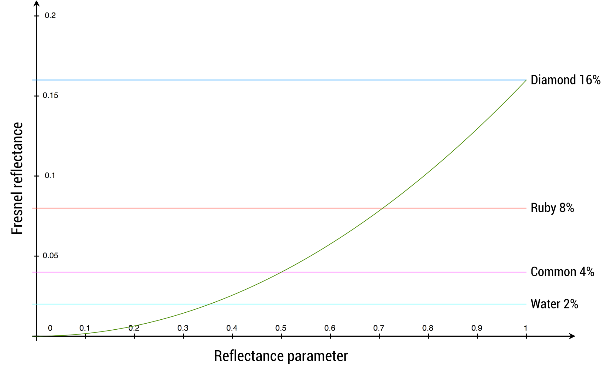
The table below describes acceptable reflectance values for various types of materials (no real world material has a value under 2%).
| Material | Reflectance | Property value |
|---|---|---|
| Water | 2% | 0.35 |
| Fabric | 4% to 5.6% | 0.5 to 0.59 |
| Common liquids | 2% to 4% | 0.35 to 0.5 |
| Common gemstones | 5% to 16% | 0.56 to 1.0 |
| Plastics, glass | 4% to 5% | 0.5 to 0.56 |
| Other dielectric materials | 2% to 5% | 0.35 to 0.56 |
| Eyes | 2.5% | 0.39 |
| Skin | 2.8% | 0.42 |
| Hair | 4.6% | 0.54 |
| Teeth | 5.8% | 0.6 |
| Default value | 4% | 0.5 |
Clear coat
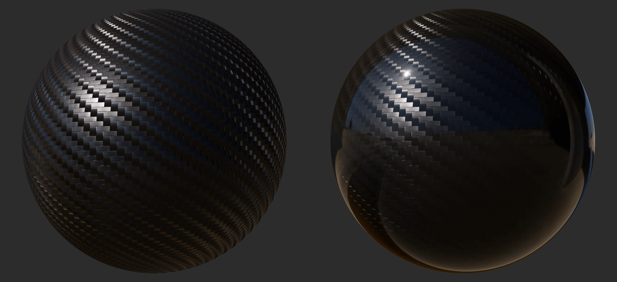
Multi-layer materials are fairly common, particularly materials with a thin translucent layer over a base layer. Real world examples of such materials include car paints, soda cans, lacquered wood, and acrylic.
The clearCoat property can be used to describe materials with two layers. The
clear coat layer will always be isotropic and dielectric. The following image
compares a carbon-fiber material under the standard material model (left) and
the clear coat model (right).
The clearCoat property controls the strength of the clear coat layer. This
should be treated as a binary value, set to either 0 or 1. Intermediate values
are useful to control transitions between parts of the surface that have a clear
coat layers and parts that don't.
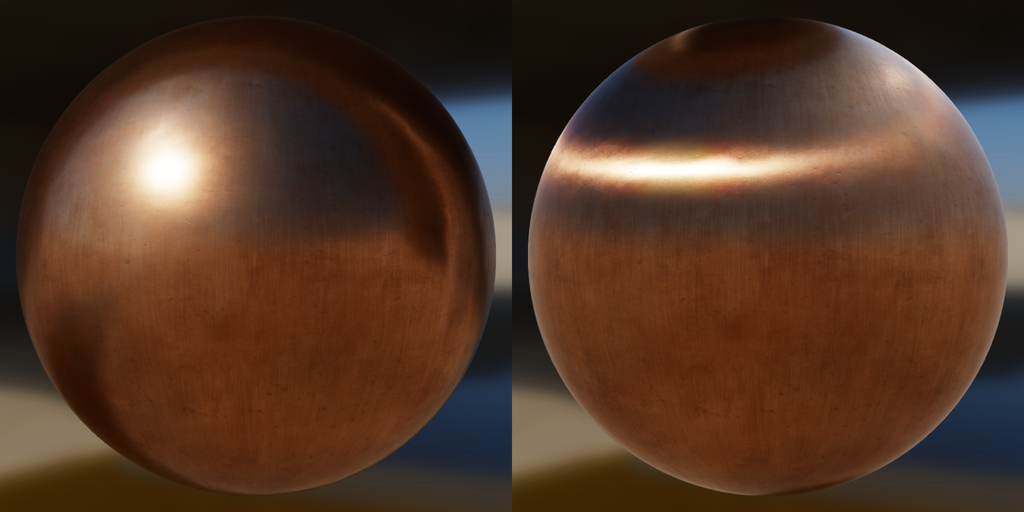
The effect of clearCoat on a rough metal is shown below (click on the image to
see a larger version).
Clear coat roughness
The clearCoatRoughness property is similar to the roughness property but
applies only to the clear coat layer. In addition, since clear coat layers are
never completely rough, the value between 0 and 1 is remapped internally to an
actual roughness of 0 to 0.6.
The effect of clearCoatRoughness on a rough metal is shown below (click on the
image to see a larger version).
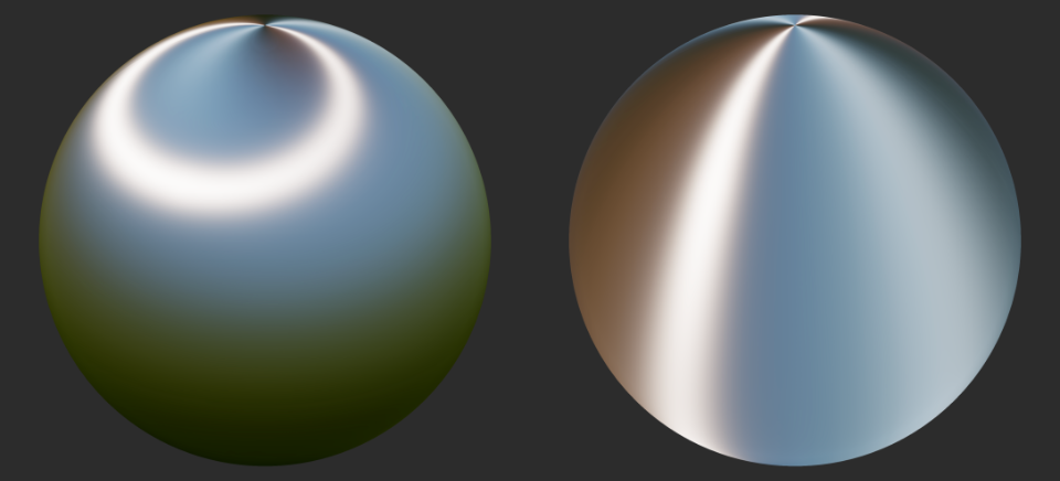
Anisotropy
Many real-world materials, such as brushed metal, can only be replicated using
an anisotropic reflectance model. A material can be changed from the default
isotropic model to an anisotropic model by using the anisotropy property. The
following image compares an isotropic material (left) and an anistropic material
(right).
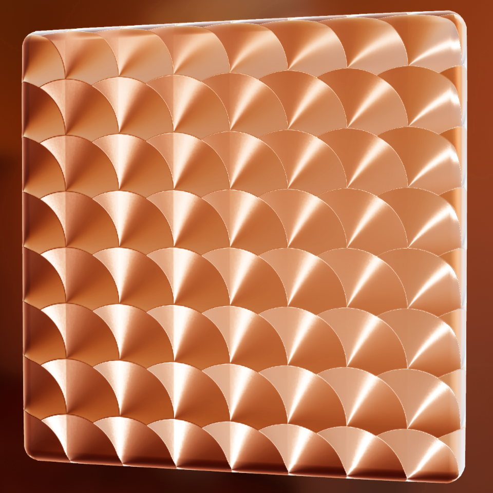
The effect of varying anisotropy from 0.0 (left) to 1.0 (right) on a rough
metal is shown below (click on the image to see a larger version).

The image below shows how the direction of the anisotropic highlights can be controlled by using either positive or negative values: positive values (left) define anisotropy in the tangent direction and negative values (right) in the bitangent direction.
Anisotropy direction
The anisotropyDirection property defines the direction of the surface at a
given point and thus control the shape of the specular highlights. It is
specified as vector of 3 values that usually come from a texture, encoding the
directions local to the surface.
The effect of rendering anisotropyDirection on a metal with a direction map is
shown below (click on the image to see a larger version).
The direction map used to render the image above is shown below.
Ambient occlusion
The ambientOcclusion property defines how much of the ambient light is
accessible to a surface point. It is a per-pixel shadowing factor between 0.0
(fully shadowed) and 1.0 (fully lit). This property only affects diffuse
indirect lighting (image-based lighting), not direct lights such as directional,
point and spot lights, nor specular lighting. The following image compares
materials without diffuse ambient occlusion (left) and with it (right).
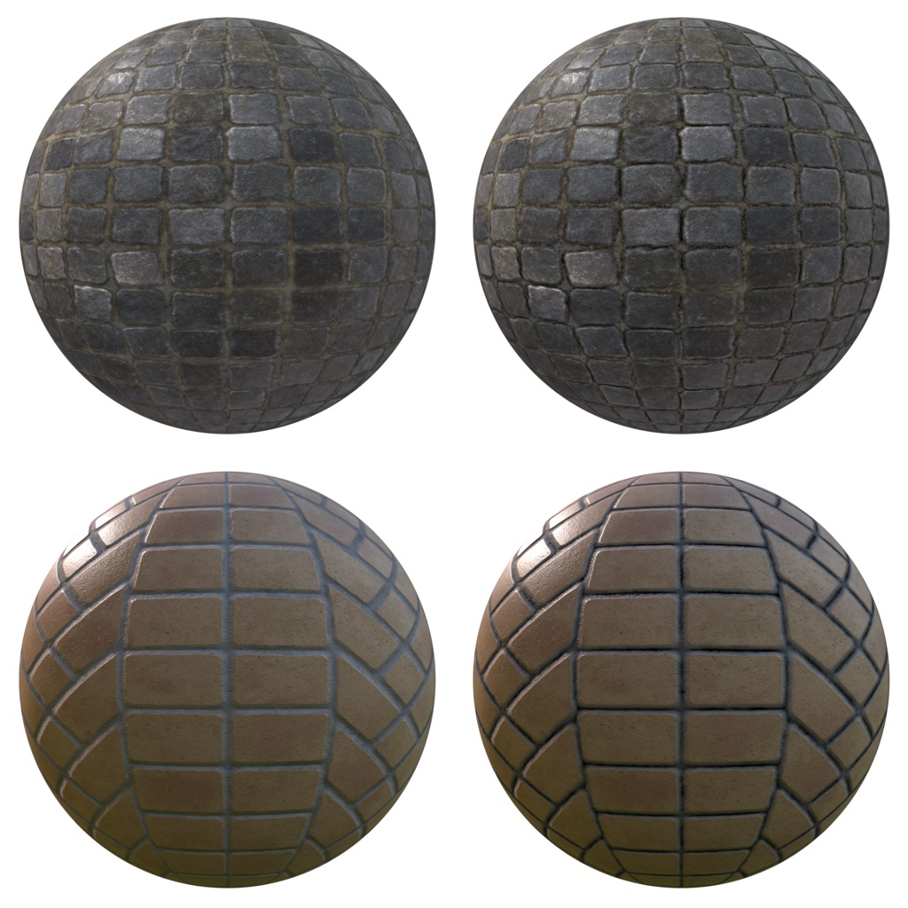
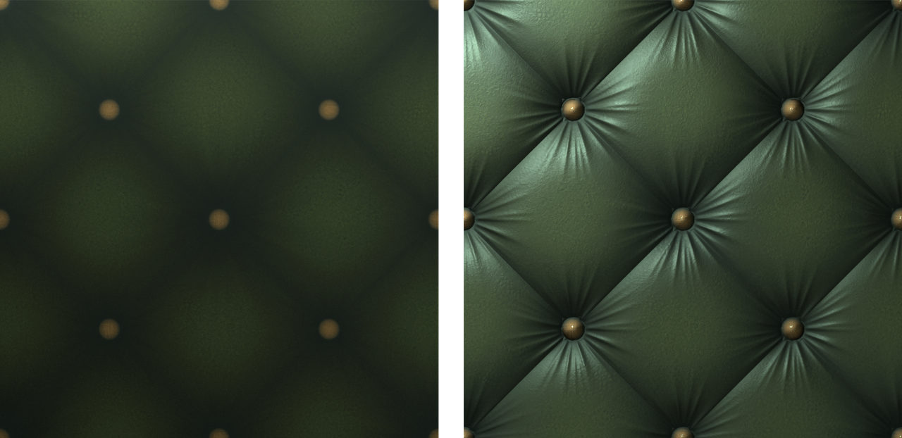
Normal
The normal property defines the normal of the surface at a given point. It
usually comes from a normal map texture, which allows to vary the property
per-pixel. The normal is supplied in tangent space, which means that +Z points
outside of the surface.
For example, let's imagine that we want to render a piece of furniture covered in tufted leather. Modeling the geometry to accurately represent the tufted pattern would require too many triangles so we instead bake a high-poly mesh into a normal map. Then you can apply the base map to a simplified mesh. The following image compares a simple mesh without normal mapping (left) and with it (right).
Note that the normal property affects the base layer and not the clear coat
layer.
Clear coat normal
The clearCoatNormal property defines the normal of the clear coat layer at a
given point. It behaves otherwise like the normal property.
Emissive
The emissive property can be used to simulate additional light emitted by the
surface. It is defined as a float4 value that contains an RGB color (in linear
space) as well as an exposure compensation value (in the alpha channel).
Even though an exposure value actually indicates combinations of camera settings, it is often used by photographers to describe light intensity. This is why cameras let photographers apply an exposure compensation to over or under-expose an image. This setting can be used for artistic control but also to achieve proper exposure (snow for instance will be exposed for as 18% middle-grey).
The exposure compensation value of the emissive property can be used to force the emissive color to be brighter (positive values) or darker (negative values) than the current exposure. If the bloom effect is enabled, using a positive exposure compensation can force the surface to bloom.
Cloth model
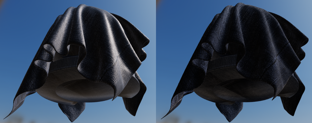
All the material models described previously are designed to simulate dense surfaces, both at a macro and at a micro level. Clothes and fabrics are however often made of loosely connected threads that absorb and scatter incident light. When compared to hard surfaces, cloth is characterized by a softer specular lob with a large falloff and the presence of fuzz lighting, caused by forward/backward scattering. Some fabrics also exhibit two-tone specular colors (velvets for instance).
The following image compares denim fabric rendered using the standard model (left) and the cloth model (right). Notice how the standard material model fails to capture the appearance of a sample of denim fabric (left). The surface appears rigid (almost plastic-like), more similar to a tarp than a piece of clothing. This also shows how important the softer specular lobe caused by absorption and scattering is to the faithful recreation of the fabric.
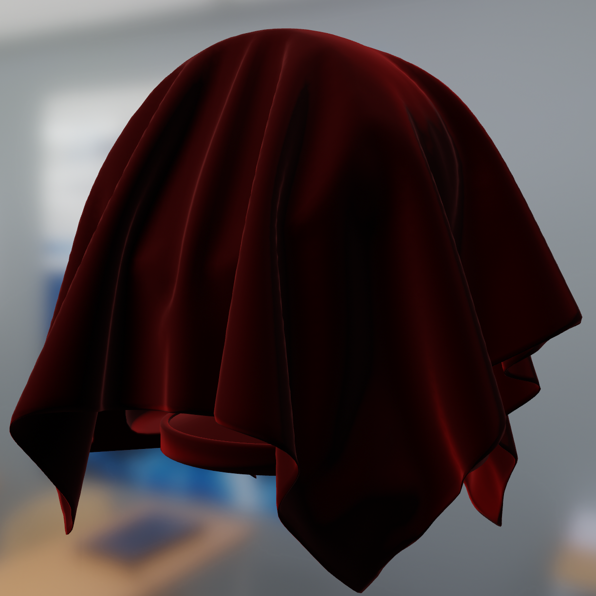
Velvet is an interesting use case for a cloth material model. As shown in the image below, this type of fabric exhibits strong rim lighting due to forward and backward scattering. These scattering events are caused by fibers standing straight at the surface of the fabric. When the incident light comes from the direction opposite to the view direction, the fibers will forward scatter the light. Similarly, when the incident light from from the same direction as the view direction, the fibers will scatter the light backward.
It is important to note that there are types of fabrics that are still best modeled by hard surface material models. For instance, leather, silk and satin can be recreated using the standard or anisotropic material models.
The cloth material model encompasses all the parameters previously defined for the standard material mode except for metallic and reflectance. Two extra parameters described in the table below are also available.
| Parameter | Definition |
|---|---|
| sheenColor | Specular tint to create two-tone specular fabrics (defaults to \(\sqrt{baseColor}\)) |
| subsurfaceColor | Tint for the diffuse color after scattering and absorption through the material |
The type and range of each property is described in the table below.
| Property | Type | Range | Note |
|---|---|---|---|
| sheenColor | float3 | [0..1] | Linear RGB |
| subsurfaceColor | float3 | [0..1] | Linear RGB |
To create a velvet-like material, the base color can be set to black (or a dark color). Chromaticity information should instead be set on the sheen color. To create more common fabrics such as denim, cotton, etc. use the base color for chromaticity and use the default sheen color or set the sheen color to the luminance of the base color.
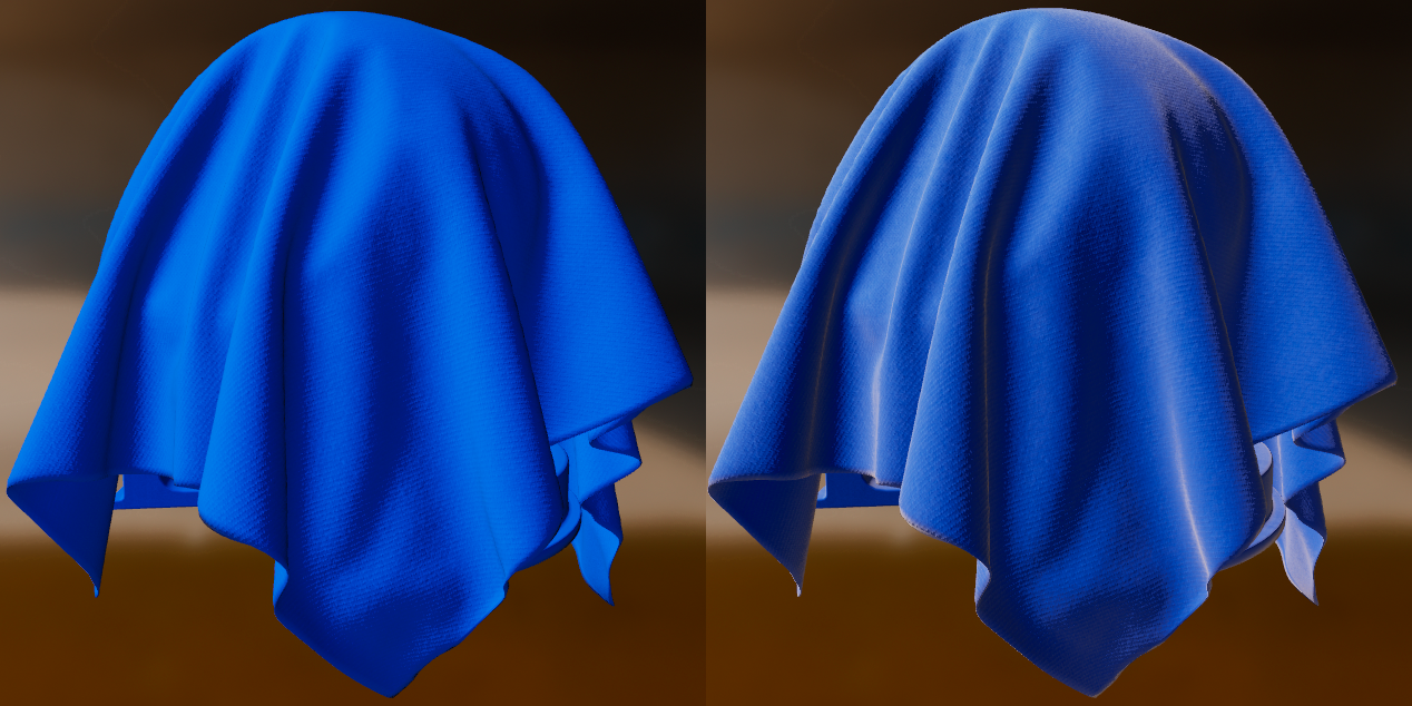
Sheen color
The sheenColor property can be used to directly modify the specular
reflectance. It offers better control over the appearance of cloth and gives
give the ability to create two-tone specular materials.
The following image compares blue fabric with and without (left) and with (right) sheen (click on the image to see a larger version).
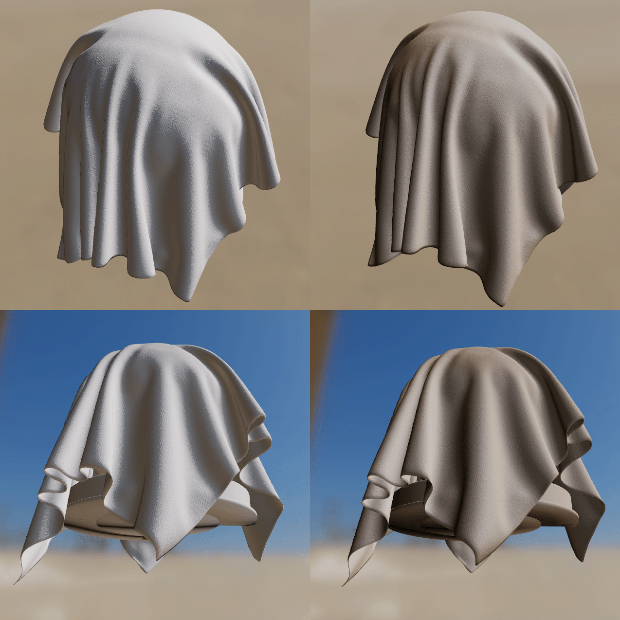
Subsurface color
The subsurfaceColor property is not physically-based and can be used to
simulate the scattering, partial absorption and re-emission of light in certain
types of fabrics. This is particularly useful to create softer fabrics.
The following image demonstrates the effect of subsurfaceColor. It shows white
cloth (left column) vs white cloth with brown subsurface scatting (right
column). Click on the image to see a larger version.
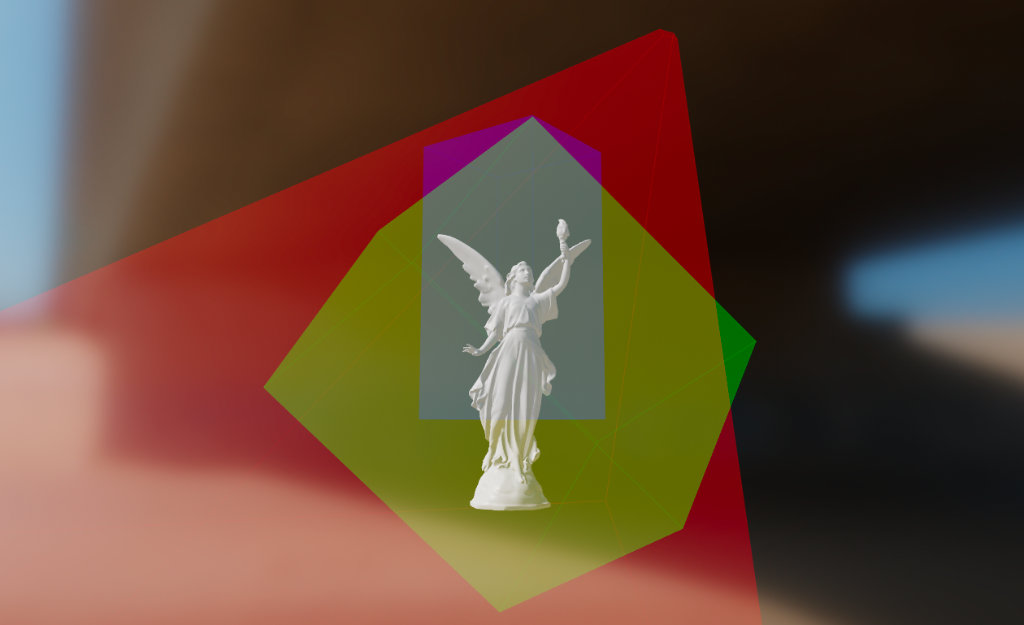
Unlit model
The unlit material model can be used to turn off all lighting computations. Its primary purpose is to render pre-lit elements such as a cubemap, external content (such as a video or camera stream), user interfaces, visualization/debugging etc. The unlit model exposes only two properties described in the table below.
| Property | Definition |
|---|---|
| baseColor | Surface diffuse color |
| emissive | Additional diffuse color to simulate emissive surfaces. This property is mostly useful in an HDR pipeline with a bloom pass |
The type and range of each property is described in the table below.
| Property | Type | Range | Note |
|---|---|---|---|
| baseColor | float4 | [0..1] | Pre-multiplied linear RGB |
| emissive | float4 | rgb=[0..1], a=N/A | Pre-multiplied linear RGB, alpha is ignored |
The value of emissive is simply added to baseColor when present. The main
use of emissive is to force an unlit surface to bloom if the HDR pipeline is
configured with a bloom pass.
The following image shows an example of the unlit material model used to render debug information (click on the image to see a larger version).
Handling colors
Linear colors
If the color data comes from a texture, simply make sure you use an sRGB texture to benefit from automatic hardware conversion from sRGB to linear. If the color data is passed as a parameter to the material you can convert from sRGB to linear by running the following algorithm on each color channel:
float sRGB_to_linear(float color) {
    return color <= 0.04045 ? color / 12.92 : pow((color + 0.055) / 1.055, 2.4);
}
Alternatively you can use one of the two cheaper but less accurate versions shown below:
// Cheaper
linearColor = pow(color, 2.2);
// Cheapest
linearColor = color * color;
Pre-multiplied alpha
A color uses pre-multiplied alpha if its RGB components are multiplied by the alpha channel:
// Compute pre-multiplied color
color.rgb *= color.a;
If the color is sampled from a texture, you can simply ensure that the texture data is pre-multiplied ahead of time. On Android, any texture uploaded from a Bitmap will be pre-multiplied by default.